
Date: Friday 29th July
Author: Amit Kumar, Technology consultant
This is the second article of our three part series on the Internet-of-Things (IoT). In the first article we have talked about what IoT is, and what the future possibilities are for this technology. In this article we are going to get hands-on and make a connected IoT device.
What do we need?
Before we start making the device , we need a couple of things to make it work:
Azure subscription
This IoT device will be connected to Azure services so you will need an Azure Subscription and ID. If you don’t already have one you can sign up for a free trial with £125 credit.
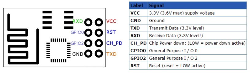
ESP8266 Wireless Transceiver Module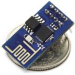
We are going to use ESP8266 to connect with Azure Services. This is a tiny device, almost size of a coin and it’s not very expensive (Purchase here).
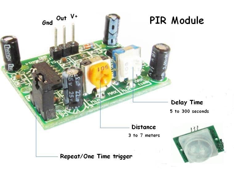
PIR Sensor Module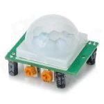
We need a PIR sensor module to detect motion and report it to ESP8266 (Purchase here).
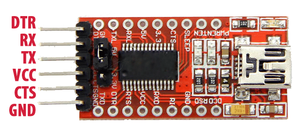
FTDI USB to TTL Serial Adapter
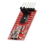 We need a FTDI adapter to connect our ESP8266 to the computer to program it. You can buy any FTDI device but try to get one which gives you 3.3 and 5v output. For this project, I am using FT232RL. This gives me 3.3 and 5v via a jumper setting (Purchase here).
A Breadboard and a Couple of Jumper Wires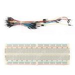
We need a breadboard and a couple of jumper wires to connect all the components together.
Breadboard power supply
This is not necessary if you want to use FTDI to power the device. However, I’d recommend to have this as it’s a handy power source for breadboard prototypes.
Building the IoT device
Now we have all the required components, we can start building our IoT device.
I have broken the build down into 4 steps to keep things simple:
- Create an Azure Mobile Service
- Know your hardware and put things together
- Program the hardware and configure it to use Azure
- See its working and monitoring the movements on Azure
Create an Azure Mobile Service
Login to Azure Portal and follow the steps below to create the Mobile Service. We use this to monitor the motion detections.
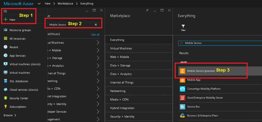
- Once you have logged-in to the Azure Portal, click on NEW (Step 1)
- In the ‘Search the marketplace’ search box, type ‘mobile service’ (Step 2)
- From the search results, click on ‘Mobile Service (preview)’ (Step 3)
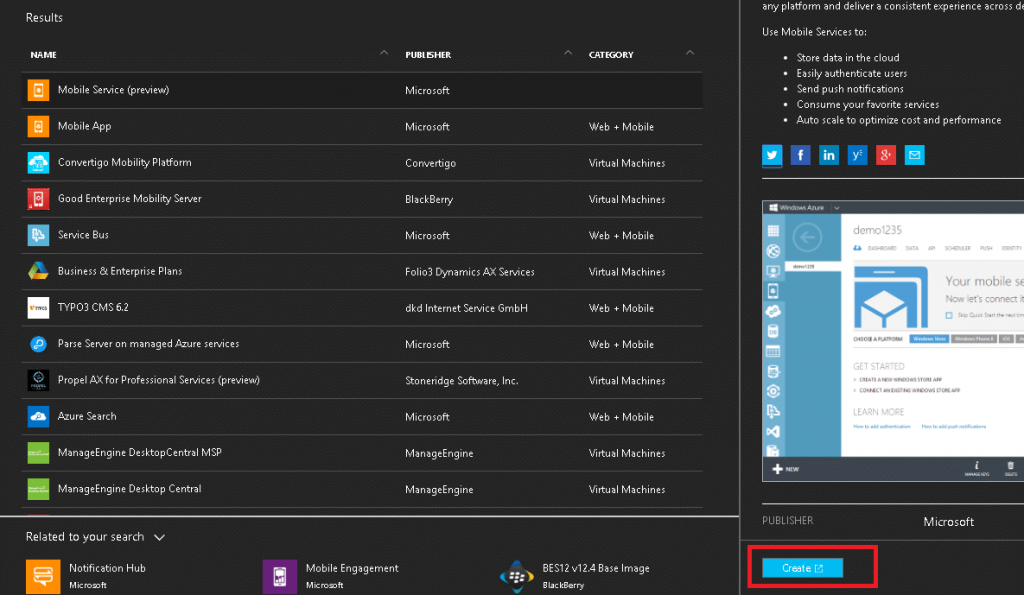
4. Click on the ‘Create’ button as shown in the screenshot below:
5. It will take you to another URL and will open the following dialog box. Please fill the details as shown in the screenshot below and click on next button:
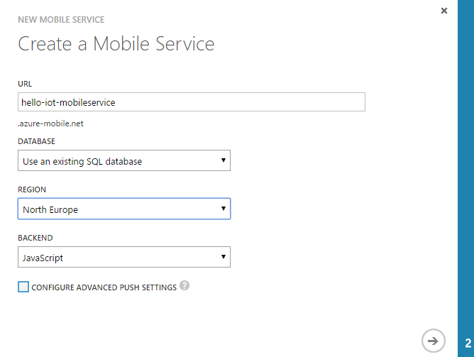
6. In this step, select ‘Create a new SQL database instance’ from the ‘Database’ dropdown and follow the steps on screen. Alternatively, you can choose any existing database if you already have one.
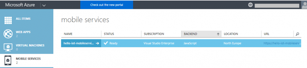
7. Once the service is created, create a table to save the data.
a. Click on Mobile Service you have just created
b. Select the DATA tab, and click on “Add a table”
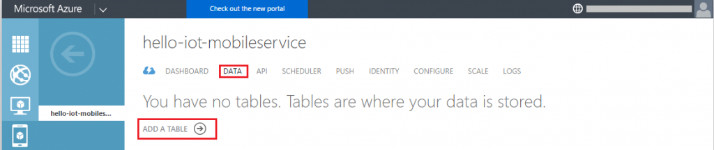
c. Create the table name “MotionLog”
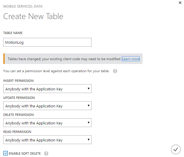
8. Create new API to connect with Mobile Service
a. Select the API tab and click on “Create a Custom API”
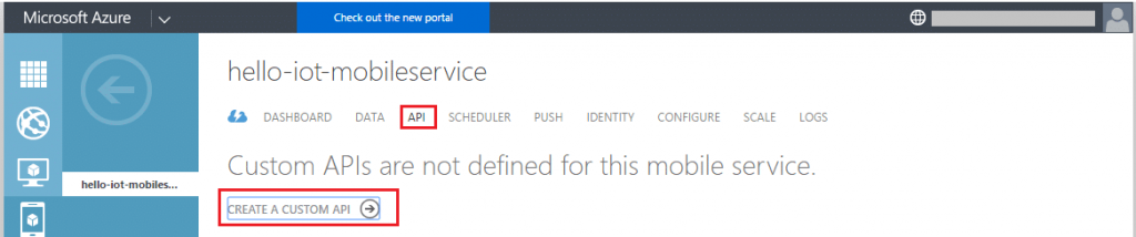
b. Name the API as “ESPAPI”

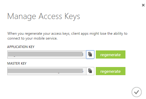
9. Select the “Dashboard” tab and Click on the ‘Manage Keys’ button to create the application keys:
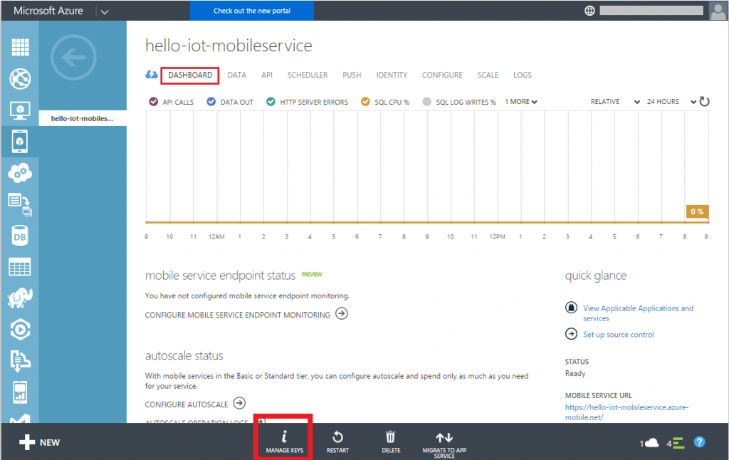
10. Copy the application key and save it somewhere in the notepad. We’ll need it shortly when we program the ESP8266.
Now, we have Azure service ready to be used in ESP8266. Let’s move on to the next step and put the hardware together.
Know your hardware and put the things together
- PIR Sensors pin outs
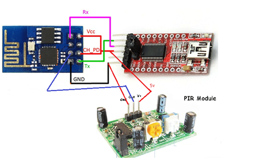
2. FTDI Serial pin outs
3. ESP8266 (01) pin outs
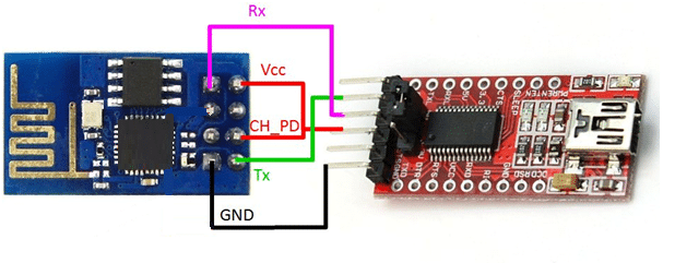
Connect the ESP to FTDI
Programme your hardware and configure to use Azure
Once we have the hardware connected, it’s time to program the ESP8266.
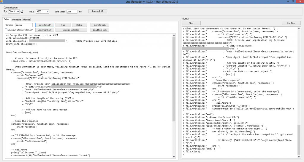
There are many ESP loader tools available and you can use any of them. I am using “Lua Uploader 1.0.2.4.” You can download it from here.
After downloading the zip file, please extract it to your local folder and double click on “LuaUploader.exe” to run the program.
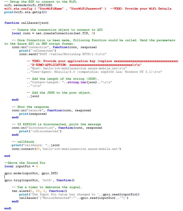
Below is the code for ESP8266. Before uploading the code to ESP, you need to change two configurations in the following scripts. The configuration values are highlighted in RED and marked as TO DOs.
The two configuration values are:
- Your WiFi name and password to connect the device to the internet
- The application key of Azure Mobile Service you created above.
Please change both the configuration and copy and paste the script in the Lua Uploader.
Now connect the FTDI Serial to the computer USB and find the USB Port in the device manager.
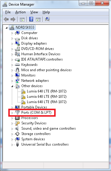
Once you know the port number, select that Port (mine is COM3 yours might be different), Baud rate and Line Delay as shown in the screenshot below:
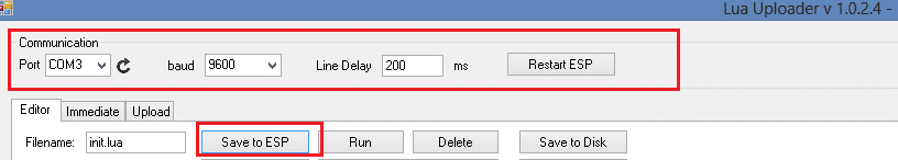
Once USB connection settings are in place, click on “Save to ESP” button. You should see a blue LED flashing in ESP8266 while program is being uploaded.
The Lua Uploader should look like this:
Now ESP8266 is programmed and ready to upload the movement’s ‘state’ to Azure Service. But before that we need to connect the PIR sensor to the ESP8266 in the next step.
See it’s working – Monitor the movements on Azure
Now you need to connect the PIR sensor and power the device. You can power the device using FTDI if you want to monitor the serial log in Lua Uploader. This is useful for debugging purpose.
Connect PIR Sensor and Power the Device using FTDI
Disconnect the FTDI from computer and connect the PIR Sensor as below. Once PIR sensor is connected, then connect the FTDI to the computer again to power the device.
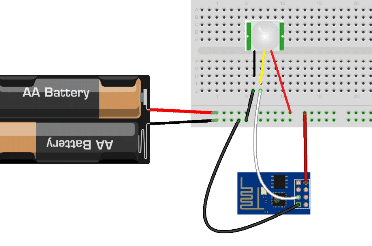
Power the device using external Power Source
If you don’t want to debug the program, then you don’t need FTDI and can power the device using the batteries or external breadboard power device. You just need to make sure you supply 5v to the PIR sensor and 3.3v to the ESP8266.

This is how you can connect the device using external power source:
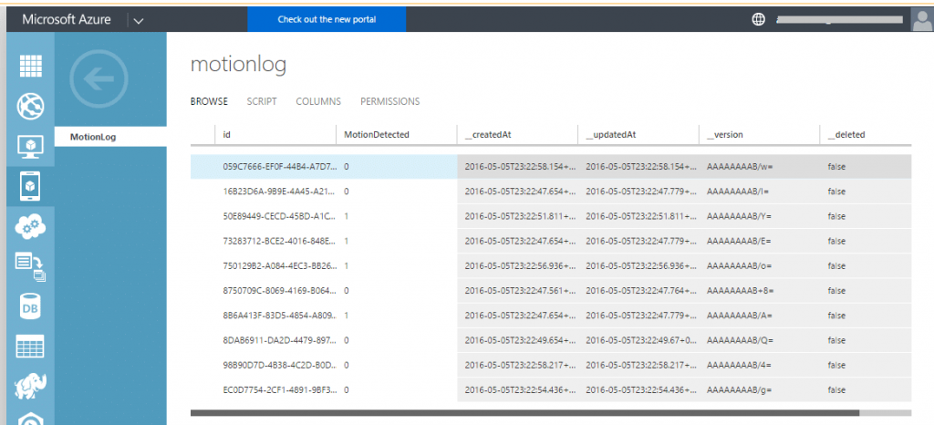
Once the device is powered on, and you put your hand in front of the PIR sensor, it’ll upload the movement’s status to the Azure.
Just go to the Mobile Application Service you created earlier and go to the DATA tab of the API. You should see the motion log as below:
With small changes in the program you can connect other sensor as well and upload the data on Azure.
Summary
This demonstration is a simple example of the power of IoT. The combination of low cost sensor components and cloud services such as Azure make this technology accessible to everyone.
To see how your organisation can benefit contact us to book your free workshop and Proof Of Concept.